Research and Development21 min read
AI Just Solved 3D. Here's How We Designed an Observatory House in Alentejo, Portugal


Early impressions of OpenAI's new GPT-6 Astra, and how well it thinks in 3D. We gave it a house, a telescope and a business case to hold at the same time.




João Montenegro, Claude, Codex and Poolside
Astra treats 3D as software
GPT-6 Astra has just been released, and we think it is a step change in how 3D gets made.
A scene is a program that outputs geometry, so you work on it the way you work on code. You can change it, check it, and change it again, at the point in a project where that is still cheap.
To see how far that goes we wanted a problem with real difficulty in it, where architecture, business, science and engineering all had to agree with each other. So we designed Casa do Poente, an observatory you can live in. A house in Alentejo. A serious telescope. And sixty piers, which are the concrete stands a telescope bolts to, rented out to people who bring their own instruments.
Then we went looking for real land, and found a smallholding near Évora with an old windmill standing on it.
A place for guests and for telescopes
We wanted bedrooms, a library and a workshop, all of it alongside the telescopes. Someone staying there who owns no equipment should be able to join a guided session. The same site also has to carry instruments doing long-exposure photography and real scientific work.
Those two things pull against each other. Guests need light to find their way, and rooms they can shut the door on. Telescopes need the opposite: darkness, an open horizon, supports that do not move, and shelter from weather and animals. A path that works for a visitor walking back at night has to stay clear of a telescope that swings.
Most of the design is working out how far apart to keep them. The library and the workshop could also host artistic work made from the observatory's own images.
Looking for a site
We went looking for real land, so that the site could argue back. We needed five things at once. A dark sky. An existing structure worth keeping. Road access we could actually use. A town close enough for guests and services. And enough ground to keep the house, the pool, the observatory and a wind turbine apart.
Évora sits inside the territory listed by Dark Sky Alqueva, which made the region a sensible place to start looking.
Most of the mill properties we found failed on size. A ruin near Portel had the land, at 4,999 m², and had already been reserved by the time we got to it. One at São Martinho das Amoreiras sat on under 800 m², nowhere near enough to keep a pool away from an observatory.
The one we designed for was a smallholding of 7,500 m² near Nossa Senhora de Machede, about twenty minutes from Évora. Flat ground, a hundred metres or so from a paved road, no services yet, and room for a house and a pool.
Then the map pin turned out to be wrong. We checked it against OrtoSat2023, the satellite mosaic published by Portugal's national mapping agency, and the pin sat inside the village while the building in the listing photographs stood about 1.1 km east of it.
So we built the ground from the imagery rather than the listing. The field and grove patterns, the farm tracks and the colours of the land are all from the mosaic. Tree heights, the mill's dimensions and the placing of house, pool, parking and turbine are ours.
Measuring sky darkness
We started with a regional light-pollution map. Satellite readings and modelled sky brightness are good for screening one location against another. What they cannot tell you is the sky over the exact spot where the telescope will stand, and that has to be measured from the spot itself. The map provider keeps the modelled and the measured data apart for that reason.
So the survey we propose points a sky-quality meter straight up, and in other directions too, at a few heights, across the seasons. Every reading logs the instrument, the time, where the Moon is, the cloud and any local lighting. Running the same tests with the house lights on and then off would show us what the building itself adds.
As you can imagine, dear reader, sky brightness impacts exposure time. It is measured in magnitudes per square arcsecond, where a higher number means a darker sky. Take a simplified case where sky glow is the limiting factor. Losing 1.3 magnitudes of darkness costs you 3.3 times as much exposure for the same result.
Calculated sensitivity and proposed field survey
Darkness is an exposure budget
No site sky-quality readings exist yet. The curve shows why measuring the proposed plot matters before exposure planning.
In a sky-background-limited example, moving from a reference sky brightness of 21.8 to 20.5 magnitudes per square arcsecond requires 3.31 times as much exposure. A field survey should measure zenith and eight bearings at two altitudes.
Exposure time rises quickly as the sky brightens
Measure the whole sky
Repeat with the house lights on and off. Log the Moon, cloud, time and instrument with every reading.
Relative model: t / t₀ = 10^[0.4(21.8 − μ)]. Fixed target, passband, optics and signal-to-noise ratio. The 21.8 value is a reference, not a claim about this site.
Which means the house can spoil a dark sky as effectively as a neighbouring town. So the lighting plan matters as much as the telescope does. Shielded fixtures, low output, and control over the light escaping through the windows. Pool lights would go off during sensitive observing. Dim red path lights would keep people moving safely, and the indoor lamps, the blinds and the screens all belong to the observing mode too. None of that is exotic; it is what DarkSky and the lighting engineers already recommend.
How we worked with Astra
Our starting prompt was a hand drawn ballpoint sketch and a narration of our goals with it. What came back was geometry we could measure and walk through.
A sketch like that used to be the start of weeks of drafting before anyone could say whether the idea held up. Now it is the whole input, and the model comes back fast enough that the first useful thing you do with it is argue.
The model is built by code. GPT-6 Astra, working in Codex, OpenAI's coding agent, writes and revises the Python scripts that assemble the Blender scene. Astra reads a note scribbled on a render, changes the geometry and renders the view again. We say what we want and judge what comes back.
We never chose that pipeline. Astra did. Put it in Codex on a machine that already has Blender on it and it starts using Blender. We already do our 3D work there, so we let it carry on.
Every technique that follows comes from treating the scene as a program, and both places we got into trouble were places we had stopped.
Draw it before you model it
The flow that worked best put images in front of geometry. We would ask Astra to generate images first, of a piece of furniture, of a room, of the house from outside, and settle the form and the materials there, where an iteration costs seconds. Only then rebuild it as geometry with the image as the reference.
It works because the two failure modes are different. An image gets proportion, material and mood wrong in ways you see instantly. Geometry gets joints, clearances and dimensions wrong in ways you cannot see until it exists.
Isolate anything you cannot steer
The first real problem was detail. Astra generates a great deal of it, very fast, and inside one large scene most of it is out of reach. You ask for a change to one chair and you find yourself negotiating with an entire house.
So we stopped asking. Furniture and other self-contained objects moved out into their own builds, one object per file, with nothing else in there to argue with. Then a wrong chair is just a wrong chair, and the fix lands in one place.
Give each isolated build its own agent
Once the builds were separate the agents could be too. We ran sub-agents against the isolated builds, and against different parts of the house, each one holding a problem small enough to stay coherent inside.
The work then went wide, narrow, wide. Pull back to the whole estate and ask whether it still makes sense. Drop into one room or one object and stay there until it is right. Pull back again. Do both at once and you get a model that is impressive in every view and wrong in all of them.
Put the fix in the component
Chairs, tables and the rest become named components, each with a fixed origin, a consistent orientation and its own geometry and materials.
The dining chair took us several goes. Early room views showed timber pieces that did not quite meet, and a cushion cutting straight through the angled posts. We repaired the frame and shaped the upholstery around it in the shared component, and every room containing that chair picked up the fix on its own.
Front and side renders of a single piece expose bad joints and proportions. Furnished plans, cutaways and eye-level views expose blocked passages, awkward doors and clashing windows.
Changes also rarely stay where you put them. Moving a fireplace away from the telescope dragged the wall, the glazing and the roof outlet along with it. Adding a bathtub meant the suite bathroom had to grow.
Expect an enormous amount of data
Astra will cheerfully produce gigabytes of Blender data, and it accumulates far faster than the thing on screen would suggest. It became a genuine problem for us, and it wants managing deliberately from the start.
Components are part of the answer, since instancing one piece of geometry across many placements costs almost nothing next to duplicating it. The stations in the observatory bays are a single shared assembly instanced sixty-odd times for that reason. The wider problem is still a live one for us.
One smaller finding, since it cost us an afternoon. We compared Blender's two renderers on matching views. A bedroom test came out at about 64 seconds in Cycles against 52 seconds in Eevee, and the lighting looked visibly different between them. Raising the sample count did not close that gap, because the two use different light transport rather than different amounts of sampling. So we kept Cycles for finished images and used the quick preview for checking camera angles.
The telescope
The telescope had to be real, because it is the object the rest of the design has to defend. We rebuilt it from the published dimensions for a PlaneWave CDK17 on an L-500 mount with an equatorial wedge, so the tube, the mount and the enclosure all sit against measurements rather than guesses. Its stated optics are a 432 mm aperture and 2,939 mm focal length. Our reconstruction covers the exterior only. The optics are quoted from the manufacturer rather than simulated.
PlaneWave Instruments drawings. Originals: CDK400, CDK17, L-500.
We have not chosen a camera yet. A sensor with 3.76 micrometre pixels would sample the sky at 0.264 arcseconds per pixel, and cover about two thirds of a degree across. At that scale you cannot fix one thing at a time. Polar alignment, pointing, focus, camera tilt, mirror alignment and tracking all have to come right together.
Optical design study
The camera turns alignment into a measurable problem
Published CDK17 dimensions are combined with an illustrative 3.76 μm, 36 × 24 mm detector. No camera has been selected.
The illustrative native sampling is 0.264 arcseconds per pixel. A calculated sensor tilt example shifts best focus by about minus 30 to plus 30 micrometres across nine sensor regions.
Sampling is a choice
432 mm aperture, 2,939 mm focal length, 0.32″ ideal Rayleigh scale at 550 nm, and a 42.1′ × 28.1′ illustrative detector field.
A small tilt shifts the best focus
Example tilts are 0.10° in x and 0.04° in y. A nine-region focus sweep and a camera rotation help separate detector tilt from the optics.
Calculated examples, not a star test. The Rayleigh value is an ideal circular-aperture scale, not delivered CDK resolution. A focus plane alone cannot diagnose collimation.
On the real system we would let everything settle to temperature first, follow the manufacturer's alignment procedure, and then collect focus sweeps and star images across the sensor. Then rotate the camera. If an uneven focus pattern rotates with it, the camera is the problem. If the pattern stays put, the fault is in the telescope. PlaneWave sets the spacing between the two mirrors at the factory, and it rarely needs adjusting.
One number carries the rest of this article. On that camera, a 0.20 arcsecond smear works out to 2.85 micrometres at the sensor. That is what a support has to hold under.
The windmill review
Putting the telescope up the windmill was the idea the whole thing started from, and it is the idea we killed.
It was going to sit on a deck above a lounge. We swung it through 208 positions in the model and none of them brought it into contact with the dome, the floor or the workstation. Geometrically, it passed.
Then we cut the tower open in Blender and saw what the drawing had been hiding. There was a concrete pier standing in the middle of the room, and the instrument was sitting directly above footsteps, warm air and an old structure we had never measured.
Keeping the telescope up there meant giving it its own route to the ground, separate from the tower and its floors, so footsteps could not reach it. A 900 mm concrete shaft, a steel box carrying the load sideways at the top, and a short stub above. As a way of carrying weight it works. As a piece of a room it is a permanent column, taking 0.64 square metres of floor before anyone allows space to walk around it, and the hatch above costs another 0.79 square metres of the observing floor.
Our checks were geometric, so we know the parts clear one another. Whether what is left counts as a usable room is another matter.
Building it would have meant digging inside an old structure, cutting holes through its floors, installing heavy steel and then raising a dome above all of that. We did look at a frame around the walls to keep the centre clear, but it just pushes the columns and foundations out towards the tower wall and then needs its own frame around the stair. That version stayed on paper.
Parametric sensitivity study
A tower can look still and still move the stars
The curves connect a general resonance example to an imaging allowance. They are not a structural model of the proposed tower.
A dimensionless oscillator with two percent damping reaches 25 times static response at resonance. A provisional 0.20 arcsecond RMS angular-motion allowance shifts the image by 2.85 micrometres at the example focal length.
Resonance amplifies a disturbance
At resonance, 2% damping gives 25× static response. The real natural frequencies, damping and forcing remain unknown.
Angular motion broadens the image
A 0.20″ angular error shifts the image by 2.85 μm, or 0.76 native pixels. With a 2.0″ baseline, this model gives 2.05″.
Left: a forced single-degree-of-freedom example, not a tower model. Right: independent Gaussian-equivalent blur, with RMS per axis. Constant pointing offsets do not blur stars.
Modelling the shaft told us something we did not expect, which is that the ground matters more than the pier. With the same shaft and an assumed 270 kg load, the lowest vibration frequency fell from 11.6 Hz on a fixed base to 7.9 Hz on a flexible one. Both come out of a simplified two-dimensional model with assumed soil stiffness, and we have not measured the real tower.
What makes it indefensible is the instrument. The tube alone lists at about $26,000, before the mount, and a 432 mm telescope resolves detail that 2.85 micrometres of movement will erase. Put that at the top of a tall slender support inside an unmeasured tower and you have spent the money and thrown away what it bought. A cheaper telescope would have tolerated the tower. This one turns it into an expensive way of taking blurred pictures.
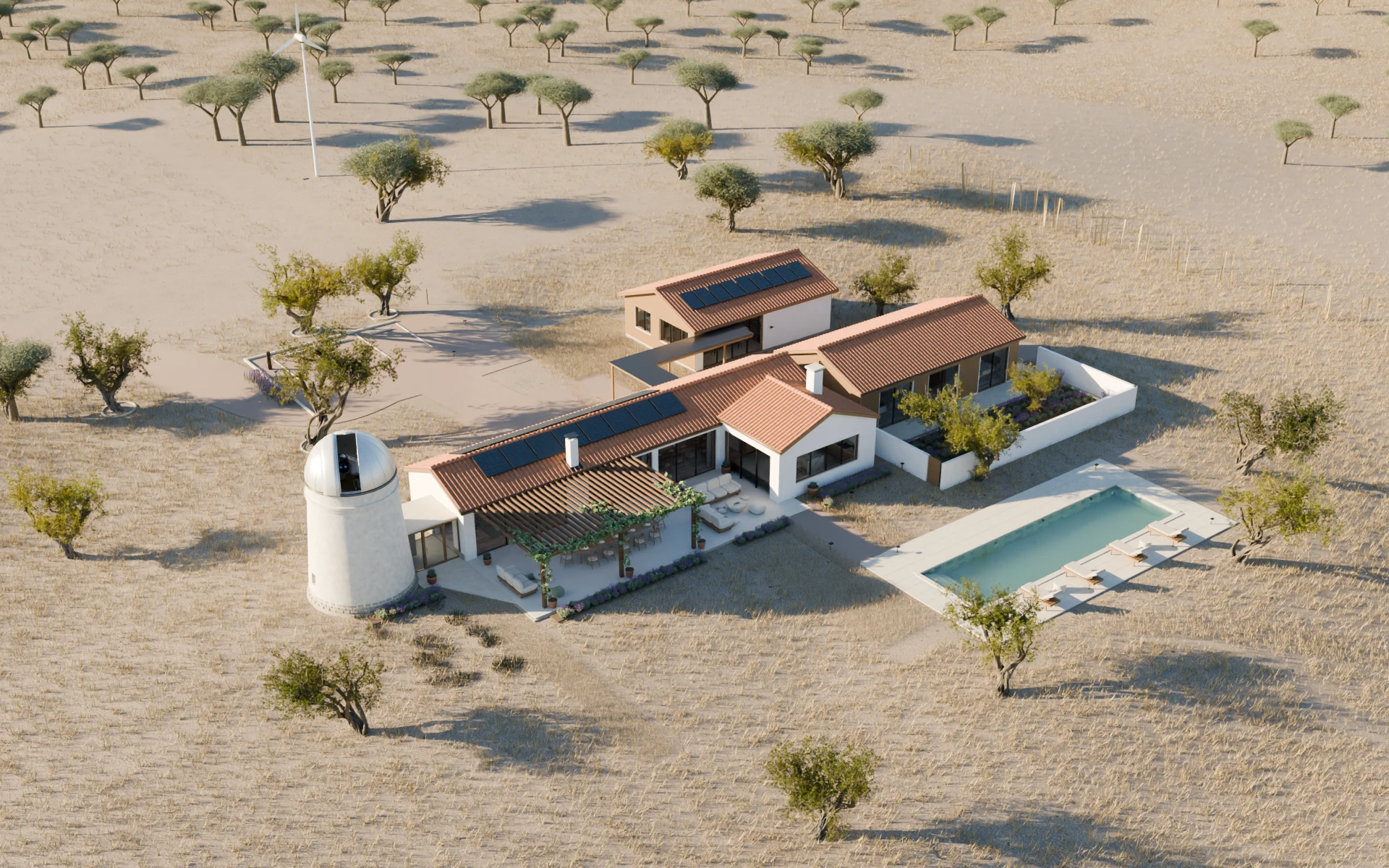
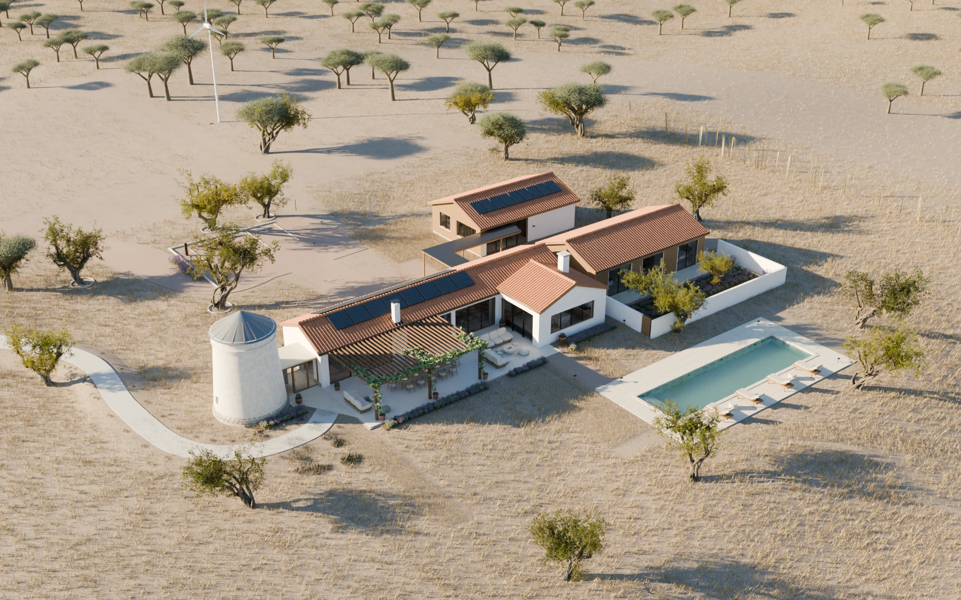
So the telescope moves to a ground-level observatory, and the windmill becomes a lounge. The revised windmill has a tall open interior under an ordinary closed roof. No dome, no observing deck, no telescope support, no stair. An earlier comparison of the two supports is still online.
Compare these separate piers and footings with the shaft that ran through the lounge.
We drew that arrangement for an earlier bay of eight piers, so the count is out of date but the principle holds. Every instrument reaches its own footing, and nothing passes through a room underneath.
Moving outside costs us land, new foundations, weather enclosures and services. What we get for it is a lounge nobody has to work around.
An observatory that can grow
Every instrument now stands on its own footing and needs nothing from its neighbours, so adding telescopes means adding piers rather than reworking the ones already there.
The site has three shared hosting bays, each one 8 by 12 metres clear. Beside them sit a room for the main telescope and a small pod for power, networking and dry servicing. Each shared bay holds twenty compact stations, four columns by five rows, which is 60 shared instruments across the three. The PlaneWave keeps its own room, and gains three companion instruments along the enlarged eastern side.
Now, sixty only exists because we shrank the customer. Every shared station reserves a radius of 0.65 metres and a height of 2.6 metres. We left the height alone and cut the radius, which used to be 1.1 metres. That cut is the entire reason twenty positions fit where eight did. Working outward from the middle, the layout keeps a 1.4 metre central aisle, then cross aisles of 1.1 metres, then half a metre between the closer paired envelopes, and at least 0.2 metres to the walls.
That envelope decides who can be a customer. Sixty holds only for equipment compact enough to live inside 0.65 metres, and says nothing about someone arriving with a larger rig.
Three generic assemblies of our own stand in for a 120 mm imaging refractor, a 200 mm reflector and an 80 mm wide-field refractor, at about 150 parts each. They are our own interpretive models rather than vendor CAD, and one shared piece of geometry is instanced across every station.
We audited the built model. In the poses we sampled, every assembly sits inside the reserved radius with a couple of millimetres to spare, and reaches 2.08 metres against the 2.6 allowed. That checks shapes standing still. It says nothing about motion, loads or any vendor requirement.
Drawn from the design record. Aisles, envelopes and wall heights are as modelled; the boundary, foundations and horizon still need site work.
The main telescope room grew from 5.4 by 5.4 metres to 6.6 by 7.2 metres to take the companions, each of which reaches its own footing through its own opening in the floor. The blocks drawn underground reserve space for footings that a ground engineer has yet to size.
Starfront's Texas facility changed how we thought about the architecture. Their photographs show fixed piers inside permanent walls, with the roofs parked outside the bays rather than sitting over them. We took that idea and turned it into permanent 1.2 metre walls, closing gates and low rails. Roof and upper side walls retract together, so nothing fixed and high ever stands over the instruments. A separate 2 metre outer fence and gated entrance add a second layer against animals.
None of that enclosure changed when the instrument count did. The roof underside still sits 3.15 metres above the finished floor, which is the clearance that matters: a mount stuck anywhere inside its own 2.6 metre envelope still passes under a closing roof.
We ran those same 208 poses again once the telescope was on the ground, this time against the room and its roof planes. That was the smaller version of the room, and the PlaneWave has not moved since, so the enlarged room still rests on the older sweep. Plenty is still open, and we would rather list it than imply otherwise. Full mount movement. Cabling. The moving walls and roof. Wind and heat shifting the short piers. Animal mesh and cable penetrations. And what the site does if a control system fails.
Neither support has been shown to hold under 2.85 micrometres.
Planning and controlling an observing night
Before sunset, a scheduler would work out which patches of sky were going to be observable and when. Through the night the observing software would hold the focus, match star patterns to confirm where the telescope was actually pointing, watch the tracking and grade each exposure as it arrived.
We calculated an example for the night of 10 September 2026 near Évora. Full astronomical darkness runs from about twenty past nine in the evening to twenty to six in the morning, on a two-minute grid. The queue holds time back for setup and closure and revisits targets, rather than assuming the whole night becomes exposure.
One-night scheduling example
A night can be planned before the roof opens
An ephemeris scan translates darkness, Moon position and target altitude into explicit observing windows and a bounded queue.
For the example night of 10 to 11 September 2026, astronomical darkness lasts roughly from 21:18 to 05:38 Lisbon time. A proposed queue schedules 21 twenty-minute blocks across four example fields, producing 315 minutes of planned integration.
The useful night is bounded by the Sun and Moon
Four example fields move through the 30° observing window
Lit cells meet all three example rules: Sun below −18°, Moon below −10° and target above 30°.
A bounded queue turns those windows into work
Twenty-one 20-minute blocks contain five 180-second exposures plus five minutes of overhead: 315 minutes of planned integration.
Calculated for 10 to 11 September 2026 at the representative plot coordinate. Field coordinates and queue are illustrative. This is not a weather forecast, and a real run would still require live weather, horizon, safety and hardware checks.
Then there is the part that has to work when nobody is watching. AI-assisted planning and interpretation live on one side of a hard line, and a simple, predictable safety layer lives on the other. Rain, unsafe wind, a stale sensor reading, a communications fault or a mains power cut all need a response that has been tested.
The hardest case turns out to be the dull one. A customer's computer or mount stops answering while the telescope is still pointing somewhere awkward, and the enclosure has to get itself to a safe state from there, with a closing sequence that cannot collide with the telescope.
The architecture we drew is proposed, not built. ASCOM, which is the standard way astronomy software talks to equipment, reports the safety state. Everything else on that diagram still has to be built and tested: the watchdog, the interlocks, the closing sequence, the backup power and the recovery policy.
Control architecture
Automation can assist the work without owning safety
The observing software is a bounded, logged executor. Independent controls detect unsafe states, force a verified safe condition and require deliberate recovery.
Planning leads into a bounded queue of solving, focusing, guiding and capture work. Normal work saves the images and system logs. Unsafe states are routed to an independent safety group that monitors conditions, reaches a safe state and restarts deliberately before saving the images and logs.
Run a bounded queue
Normal completion
Independent safety
Unsafe state · after checks
ASCOM safety state is an interface, not a complete safety system. Closure order and fault tolerance must be designed for the actual mount, shutter and power hardware.
The morning report could carry the calibrated images, the conditions each exposure was taken in, and the reason any frame was rejected. AI would write the account of the night from the images and their recorded data. On a cloudy night it would write down why observing stopped.
What telescope hosting would have to earn
Portugal already does this. Dark Sky Alqueva is a Starlight Tourism Destination with its own observing experiences and hospitality partners, and there are established astrotourism operators. What Casa do Poente explores is more intimate than any of that. One property, with its own observatory.
Customers bring their own instruments, and we supply protected space, power, connectivity and technical support. The PlaneWave stays out of it, as a separate first instrument for commissioning, science and guest use, so none of what it might earn props up the hosting figures.
Three operators give us a market to read. Starfront in Texas charges between one hundred and fifty and four hundred US dollars a month for a dedicated pier, depending on how much swing you are allowed. Astro ARO in Portugal, a nonprofit association, starts at €280 including VAT, which is about €228 net. PixelSkies in Spain charges €300 plus VAT, but for two telescopes and two cameras on the same pier, so about €150 an instrument.
That last comparison is the uncomfortable one, and you should hold onto it. We are proposing more than twice the Spanish price per instrument, at a site with no track record.
We settled on €335 net per position per month and swept from €225 to €500 around it. At 51 paying customers, which is 85% of sixty, that is about €205,000 a year. The ramp starts at 21 paying customers and reaches 51 by year five.
Against it we costed the three bays, the pier circuits, the shared site works, maintenance, a major renewal in year six, and the people to run sixty positions rather than a smaller site. The lean case allows three quarters of a full-time person on site, the base case one and a quarter, the high case two. None of it is quoted yet. These are assumptions to take to operators and suppliers and be argued out of.
60-position operating target
The business case begins with 60 hosted telescopes
Three bays of 20 compact positions are the design target. The commercial test asks whether 51 paying customers at steady occupancy can support the site, not whether a smaller campus can be made to work.
The design provides 60 hosted telescope positions. At 85 percent steady occupancy, 51 paying customers at 335 euros net per month produce 205 thousand euros of annual revenue. Under unquoted assumptions, annual operating cash is positive in the lean and base cost cases and negative in the high case.
Installed positions
60
Paying at 85%
51
Net monthly target
€335
Annual revenue at target
€205k
Base demand ramp
Annual operating cash at the steady target
At €335 net per occupied position each month, before debt, tax and the initial build.
Positive annual cash does not by itself repay the initial capital. The ten-year test below includes the build, maintenance and a year-six renewal allowance.
Illustrative constant-2026-euro model, excluding VAT, finance, income tax, property acquisition, house renovation and customer-owned equipment. The 60-position staffing assumptions are 0.75, 1.25 and 2.0 loaded on-site FTE across the lean, base and high cases. All inputs still need supplier quotes and operating validation.
What the costing came back with is that the price is fine and the build is everything.
At €335 and 85% full, the lean case throws off about €144,000 a year, and a ten-year net present value of about €457,000. The base case still makes €79,000 a year, but its heavier construction and staffing put its ten-year value €263,000 below zero. The high case loses money on operating cash before any construction is counted.
So what the exercise really produces is a budget. At €335 the lean case can afford about €718,000 of all-in initial capital, comfortably above the €299,000 it wants to spend. The base case can afford only €352,000 against a €588,000 allowance, and would need €413 a month to break even over ten years. The high case would need €739 a month, outside anything we are testing.
60-position capital test
Price and build cost have to meet
Each curve shows the maximum all-in initial capital that ten years of hosting can support as price changes. The marker is the €335 net monthly target.
At 335 euros net per occupied position per month, the lean case supports about 718 thousand euros of all-in initial capital against a 299 thousand euro allowance. The base case supports about 352 thousand euros against a 588 thousand euro allowance and would need about 413 euros per month to break even. The high case does not support positive initial capital at the target price.
Lean cost case
€718k ceiling
Against €299k of assumed initial capital. Clears the ten-year hurdle at €335.
Zero-NPV price: €201/month
Base cost case
€352k ceiling
Against €588k of assumed initial capital. Does not clear the ten-year hurdle at €335.
Zero-NPV price: €413/month
High cost case
−€210k ceiling
Against €963k of assumed initial capital. Does not clear the ten-year hurdle at €335.
Zero-NPV price: €739/month
Hosting only, with customer equipment excluded. The calculation uses the base demand ramp, an 8% real discount rate, routine maintenance and a year-six renewal. Capital ceilings are decision limits, not budgets or supplier quotations.
Only the lean case survives that test. What is still unproven is whether real customer telescopes fit inside 0.65 metres, and whether sixty people want a pier in Alentejo.
What Astra changed
The study took two days, fitted around other work. For a sense of what that replaces, Klopf Architecture publishes its own project schedule and puts the initial design of a new house at about a month or more. That is the house on its own, before the telescope, the optics, the enclosure or the business case.
The speed is the smallest part of it.
Astra held a project with architecture, structural reasoning, optics, scheduling and a business case in it, and let us move between them without any of it coming apart. What came back had dimensions on it, and dimensions are something you can argue with.
A tool that only made renders would have left the dome on the windmill, because the dome looks wonderful and a render never complains. What took it off was cutting the tower open and running a number, and both were cheap enough to do on a whim.
None of it is built. The reasoning is what we are publishing, reversals included.
So take the method, dear reader, and try it on something of your own. And if you would like to develop an idea with us, talk to Darkmatter.
Darkmatter is a hardware, software and AI lab based at Poolside Santos in Lisbon.
A few views from the model
Six more views, from before the observatory moved. Where a dome still sits on the windmill, that is the tower we cancelled.
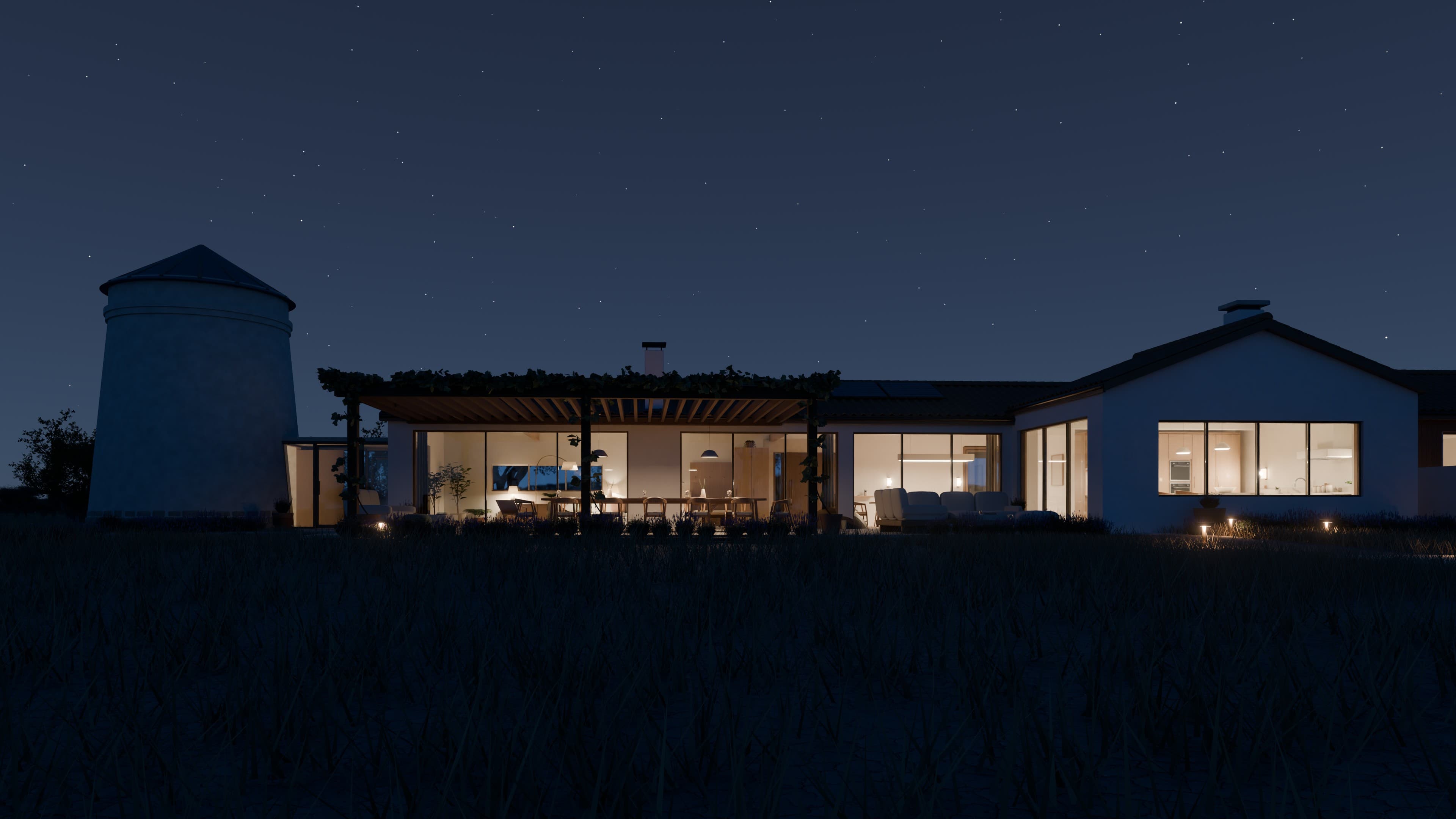
Pool: the evening leisure lighting. Sensitive observing would use a different state.
The Milky Way behind the tower is an illustration, ESO/S. Brunier, CC BY 4.0, placed into the render rather than photographed on site.