Research and Development7 min read
Can AI agents build a digital twin of an aircraft? We tested it


We asked two AI agents to build a digital twin of a real aircraft, then tested it like engineers would. What worked, what did not, and why it matters.




João Montenegro, Claude, Codex and Darkmatter
Almost every new car, aircraft and medical device starts life as a detailed 3D model on a computer. Before a single part is made, engineers can spend months building those models in specialised design software. It's skilled, slow work.
That's starting to change. The AI models that learned to write essays and computer code are now being pointed at physical design. Autodesk, one of the biggest names in design software, now lets Anthropic's Claude build 3D shapes inside its tools. Start-ups are promising AI agents that turn a written brief into engineering designs. If that works, it could change how quickly the physical world gets built.
But there's a catch. A design that looks right and a design that works are different things, and AI is good at producing things that look right. Engineers know it. In a 2026 survey of about four hundred American engineers and engineering students, more than eight in ten said they use AI, but only six in a hundred trusted its answers without checking. So the real question isn't whether AI can draw a machine. It's whether you can believe what it draws.
We wanted to find out on something hard. So we asked two of the most capable AI models available to build a digital twin of an aircraft, and then we checked their work the way an engineering team would.
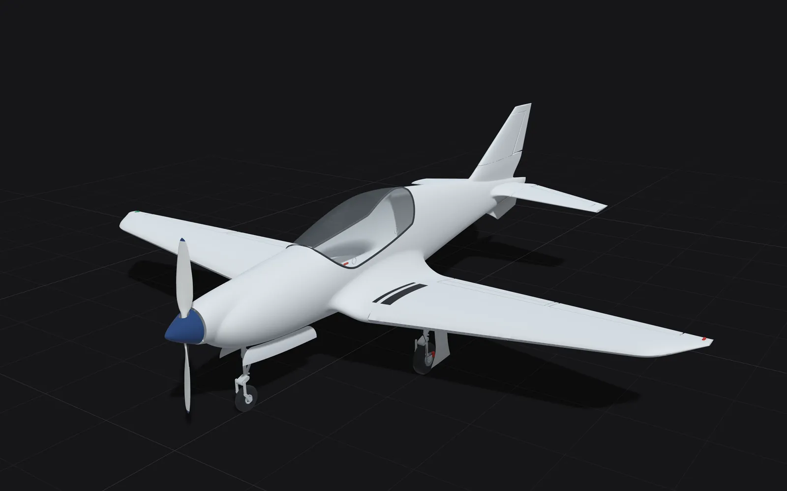
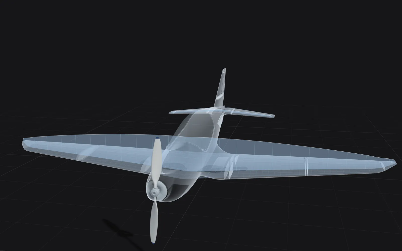
The detailed numbers sit in the margin beside each section, and the aircraft below is the model itself: turn it, cut it open and move its controls.
Explore
The whole model in one viewer
Switch between paint, metal, zebra and curvature views, show the patch boundaries, cut sections and jump between views.
Render
Layers, section and view
Drag to orbit, shift-drag to pan, Ctrl or Command and scroll to zoom. The zebra and metal shading follow our open-source CAD Viewer, github.com/JMMonte/cad-viewer.
The experiment
- Built by GPT-6 Astra and Claude Opus 5.5, in a harness we built that lets an agent construct geometry as code, and rendered in Blender.
- 30 numbered revisions over 41 hours, from the first save to the last.
- The final aircraft rebuilds from its saved inputs in 187 seconds, and its four model files come out identical, byte for byte.
- An independent reconstruction of the Blackshape Prime from a brochure, the flight manual and photographs. Blackshape was not involved.
- LEAP 71, which designs rocket engines in code, argues that flight hardware needs this kind of determinism. 3D ADEPT, Jul 2026
- We used the same approach for a house. Geometry as code
A digital twin is a virtual copy of a machine, detailed enough to inspect, move and test as if it were the real thing. NASA described the idea more than a decade ago: a model of one particular vehicle, kept up to date with data from the real thing.
We chose a real aircraft, a two-seat light aircraft called the Blackshape Prime, and gave the AI only what anyone could find in public: a brochure, the flight manual and photographs. The manufacturer wasn't involved.
An aircraft makes a demanding test. The outer skin has to be smooth enough for air to flow cleanly over it. Many parts have to move without hitting each other. The engine, the fuel and two people all have to fit inside a tight shell. And in the end, the thing has to fly.
The two AI agents, one running OpenAI's GPT-6 Astra and one running Anthropic's Claude Opus 5.5, didn't use the design software engineers normally use. They wrote the aircraft as code: small programs that generate every curve and every part. We built the system that let them do it. Then we tested what came out.
What the agents built
In forty-one hours, across thirty versions, the agents produced a whole aircraft: an outer skin, a two-seat cockpit, controls that move, landing gear that folds away, a simplified engine and fuel tanks. Because the whole thing is code, it can be rebuilt from its saved inputs in about three minutes, and when we did that, every file came out identical.
And it looked right. That turned out to be the problem.
Where looking right wasn't enough
- Revision 1: the wing-root blends matched their neighbours to 2.8 micrometres in position, and in angle and curvature, and a review rejected them. They were removed in revision 2 and rebuilt later.
- Revision 6: on the nose, the curvature on the two sides of one seam differed by a factor of 10. We rebuilt a 76 mm band on each side; the surface moved by at most 1.04 mm.
- Abrupt changes in curvature can also disturb the airflow near a stall.
- StepToCut reports a checking script that printed all clear on a drawing a person rejected within seconds.
- On a Class A surface, neighbouring patches match in position, angle and curvature along every seam meant to be smooth.
- 44 fuselage seams measured: the median angle between the two sides is 0.09°, and nine in ten are within 0.43°. The test's own noise is 0.05°.
- Three seams on one fuselage section measure 0.8 to 1.5° and are first in line for review. Class A sign-off for the whole aircraft is still ahead.
- OpenAI reports 95.9% shape overlap for GPT-6 Astra on BenchCAD, which scores single parts rebuilt from four views by writing CAD code. Anthropic reports 0.962 for Claude Opus 5.5 on the same task. OpenAI and Anthropic, 2026 (vendor-reported)
- In the benchmark paper's own runs, frontier models of May 2026 without tools scored 0.19 to 0.28 on that task. BenchCAD, May 2026 (independent test)
- Of 1,030 generated programs that ran, 432 met the stated engineering requirements. CADEngBench, Aug 2026 (independent test)
Early on, the agents built the curved pieces that join each wing to the body. Those pieces passed every numerical test we had. Where they met the surfaces around them, they lined up to within three thousandths of a millimetre, far finer than a human hair. A design review rejected them anyway. The tests had checked the edges. None of them checked whether reflections would flow smoothly across the whole shape, or whether its pieces were laid out sensibly. Those pieces had to be built again.
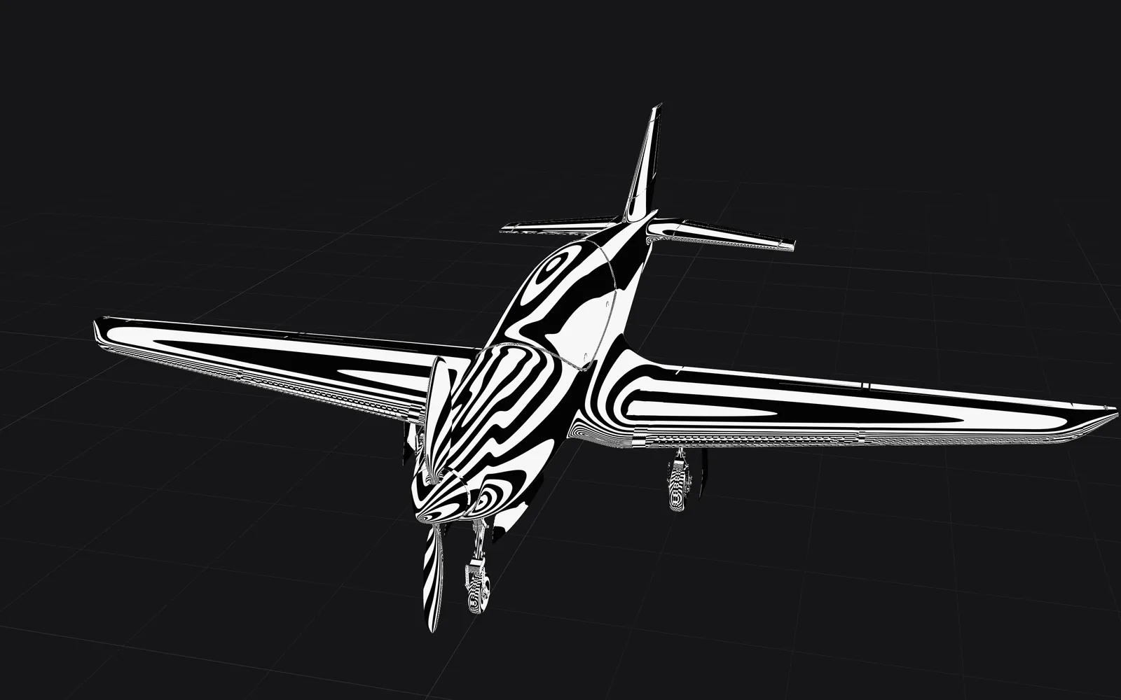
To catch what the numbers miss, we borrowed a trick from car design. Designers reflect straight stripes of light across a car's body. On a smooth surface, the stripes flow across every join without a break. Where two surfaces don't quite match, a stripe kinks, and the eye catches it at once.
Zebra stripes
The skin reflecting a striped light
Look at the nose and where the wings meet the body. On a smooth surface, the stripes run unbroken across every seam. Drag to turn the aircraft; the sliders change the stripes and the light.
Reflection
Overlay
The patch lines mark the boundaries between the surface patches the skin is built from.
The stripes found a flaw on the aircraft's nose that ordinary shading had hidden completely. Two surfaces met at the same point and the same angle, but one bent ten times more sharply than the other, like a gentle curve in a road meeting a sharp one. The fix moved the surface by a millimetre at most.
Curvature
Where the skin bends
Colour shows how the skin bends. On the Gaussian setting, ochre bulges outward, like the nose. Blue curves up one way and down the other, like a saddle, where the wings meet the body. Grey is flat in one direction, like the wing panels. The Mean setting colours outward bends ochre and inward bends blue. Show the patch lines to see where the colours change across a seam.
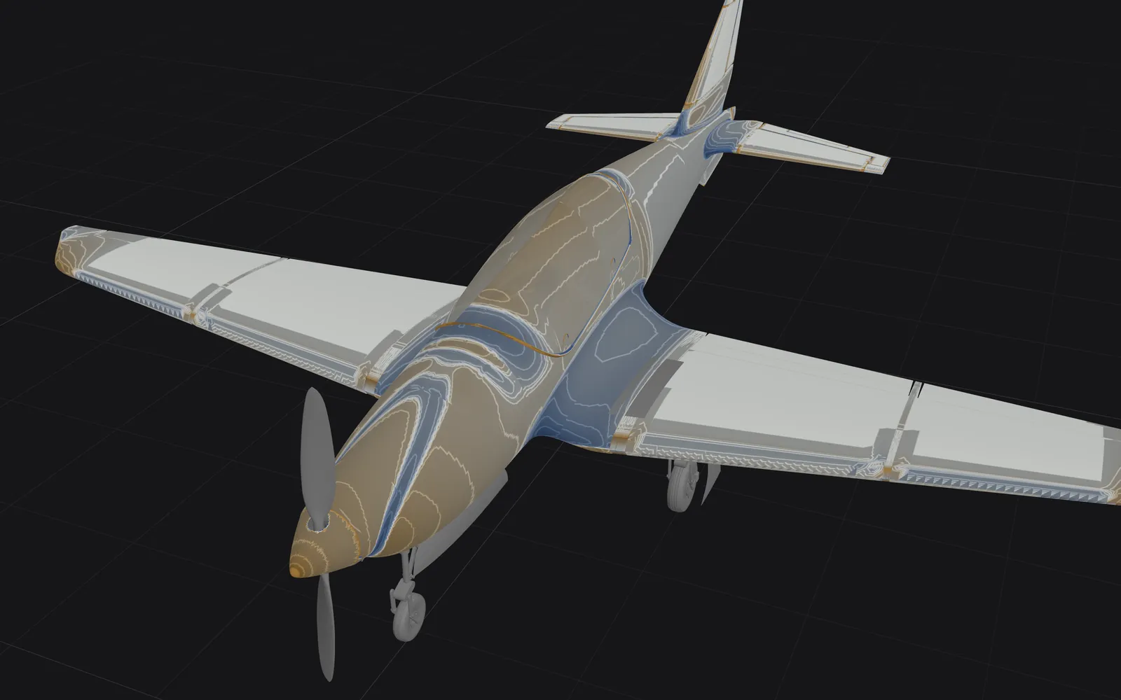
Curvature map
Overlay
Curvature is computed patch by patch from each patch's own shape, wherever that calculation works, so the triangles of the mesh do not show up as curvature and a seam can show a different value on each side. The colour scale is symmetric and logarithmic.
What turned up inside
- Tail controls: 91 sampled positions, one control at a time. Landing gear: six covers and twelve hinges through 49 positions. No unintended contact was detected.
- Hinge positions are inferred from the modelled hardware: the flight manual gives each control's travel, but not where its hinges sit.
- Inside: a Rotax engine with its cooling, two 33-litre fuel tanks and three landing gear units. The engine's output sits 245 mm behind the propeller and the hub covers 85 mm, leaving a 160 mm drive connection to design. Hoses, a cooling line and the exhaust touch their neighbours in 21 places.
- Cockpit: pilots of 1.60, 1.75 and 1.90 m in both seats. Reach to spare at stick and throttle, 62 to 129 mm; head clearance, 77 to 211 mm; pedal adjustment, 160 mm in front and 85 mm behind.
- Across 150 joint pairs and eight older models, the best one got the full joint, frame and motion right 15.8% of the time. CADEngBench, Aug 2026 (independent test)
- On 25 assembly tasks, an agent running GPT-5.5 recovered 0.28 of the solid volume. RealCADBench, 3 Sep 2026 (independent test)
Next, we made it move. We swung the tail controls through their travel and cycled the landing gear, checking for collisions at a hundred and forty positions. We found none, though we had to estimate where the hinges sit.
Moving parts
Controls, canopy and landing gear
Move the controls, or play the landing gear cycle and watch the covers and legs move in sequence.
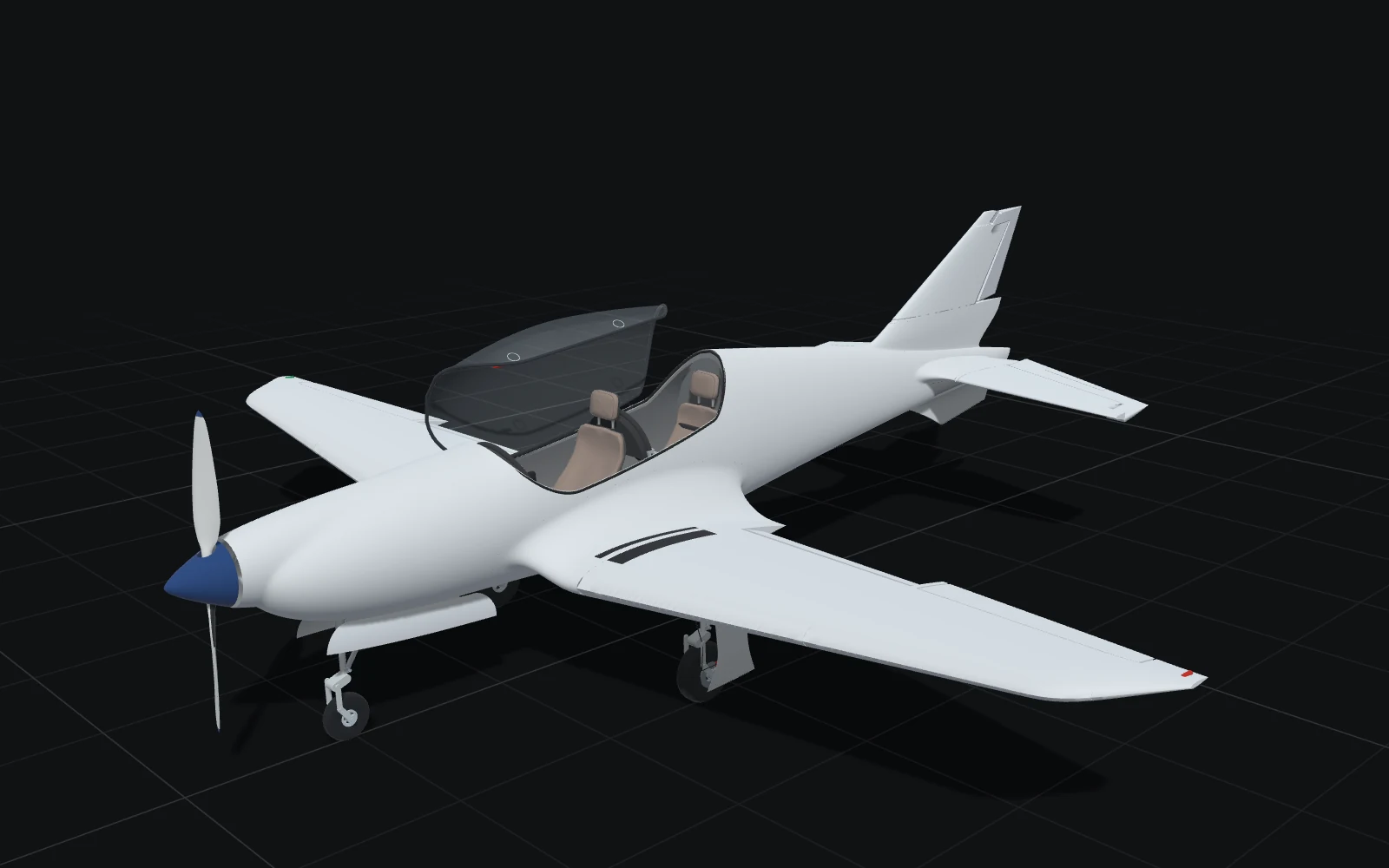
Flight controls
Canopy, gear and propeller
Control travel is from the flight manual. The gear sequence, hinge positions and clearances are inferred from our hardware model.
Then we looked inside, and three problems turned up. The engine sat sixteen centimetres short of the propeller, so a part to connect them still has to be designed. Hoses, a cooling line and the exhaust were touching their neighbours in twenty-one places. And the seat belts, drawn as worn, passed straight through the pilots' bodies.
Each problem turned up only because we ran a check aimed at it.
Interior
Seats, engine, fuel tanks and landing gear
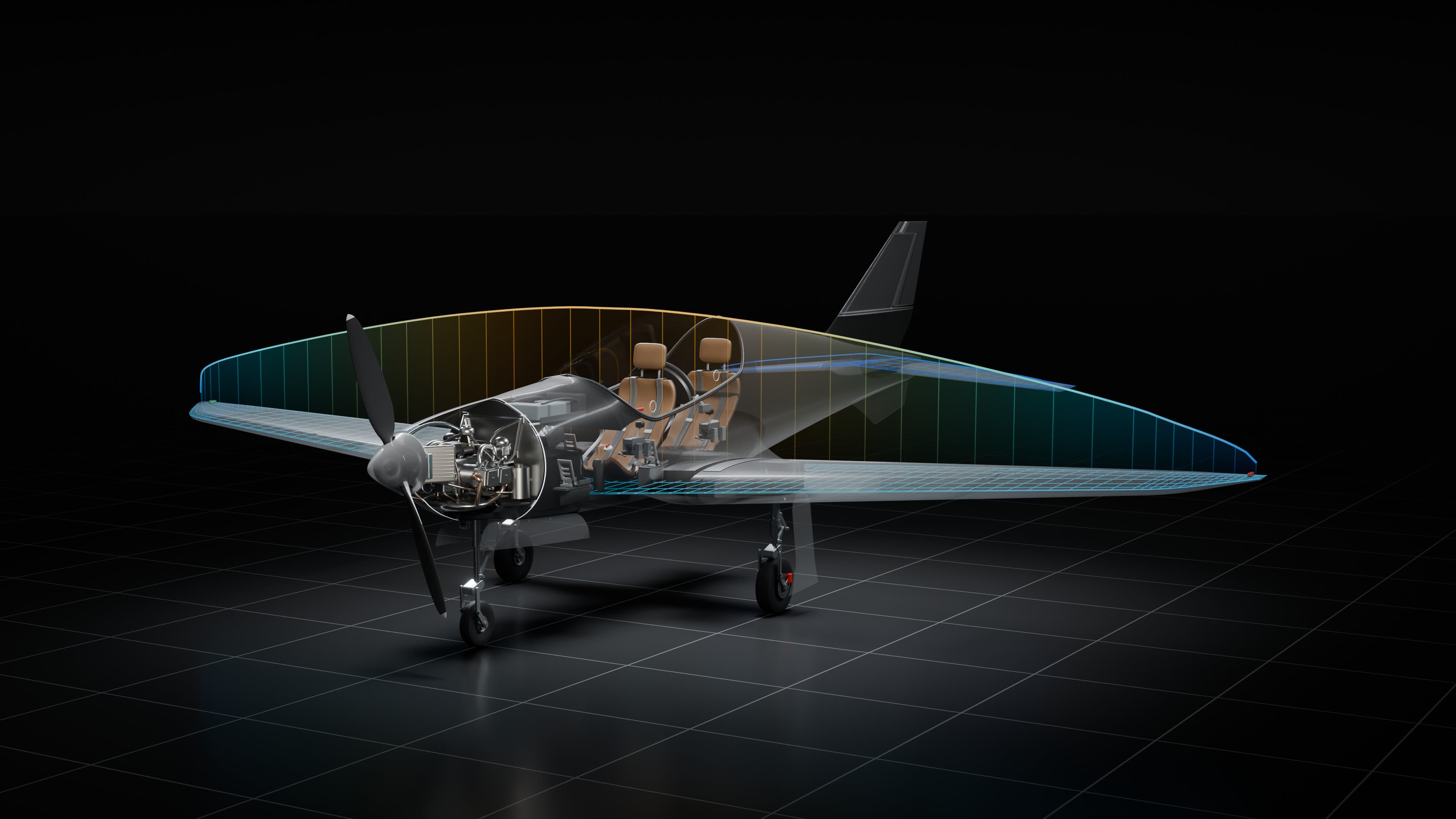
See through the skin and slice the aircraft open. Switch on the layers to find the engine, tanks and landing gear in their bays.
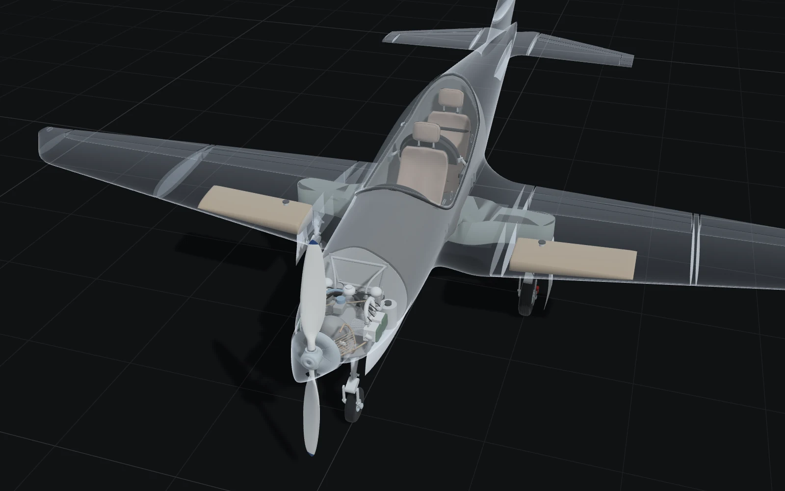
Layers
Section
The engine is a simplified stand-in for its size and shape, not the manufacturer's design. The harnesses and pilots are left out of this view.
We also sat virtual pilots of different heights in the cockpit, from one metre sixty to one metre ninety. All of them could reach the stick and the throttle. The tallest, in the front seat, had the least headroom, just under eight centimetres, and that needs a closer look.
Cockpit fit
Three pilot sizes in two seats
Pick a pilot height and a seat. The vertical line shows the gap between the top of the head and the canopy glass, and the table gives the measurements for the pilots shown.
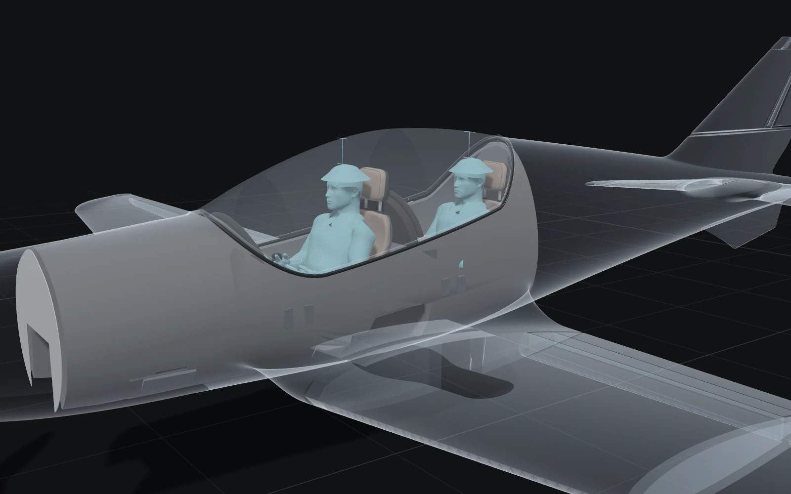
Occupants
Show
- 1.75 m, front
- Head to canopy
- 132 mm
- Reach reserve, stick
- 114 mm
- Reach reserve, throttle
- 84 mm
- Knee angle
- 154°
- Pedal adjustment
- 0 mm
- 1.75 m, rear
- Head to canopy
- 147 mm
- Reach reserve, stick
- 120 mm
- Reach reserve, throttle
- 98 mm
- Knee angle
- 138°
- Pedal adjustment
- −10 mm
| Occupant | Head to canopy | Reach reserve, stick | Reach reserve, throttle | Knee angle | Pedal adjustment |
|---|---|---|---|---|---|
| 1.75 m, front | 132 mm | 114 mm | 84 mm | 154° | 0 mm |
| 1.75 m, rear | 147 mm | 120 mm | 98 mm | 138° | −10 mm |
The body is the pilot model from the FlightGear DG-101G glider (the aircraft is by Nikolaus Kerner and FlightGear contributors, github.com/FGMEMBERS/DG-101G), rescaled by the study to three statures with the model's shoes and cap, and reduced here to 14,000 triangles each. It stands in for body shape and is not measured anthropometry. Head clearance is measured to the top of the cap. Pedal adjustment is how far the study moved the pedals from their modelled position to fit each pilot.
Would it fly?
- VSPAERO 7.2.2 in OpenVSP 3.51.3, treating the wing and horizontal tail as thin sheets of panels, at 51 m/s (about 184 km/h) and angles from −2 to 6°. The geometry is from revision 9, within 6 mm of revision 30 away from the wing root.
- Three of five angles met the limit we set on the solver's leftover error. Lift slope: 0.088 per degree, against 0.091 to 0.094 from a thin-sheet textbook estimate.
- A second run with three times as many iterations reproduces the first. At 3°, lift is about 97% of what the maximum mass of 472.5 kg needs.
- Pitching moment slope: −0.0169 per degree. A hand estimate and a second solver we wrote give slopes steeper by about 20% and 45%. The two induced-drag estimates differ by 72%.
- In the authors' own OpenFOAM benchmark, 88% of basic runs executed but 42% reached an accurate flow field, on older models. Foam-Agent, 2026 revision (authors' own test)
- In another group's test, some meshes silently left out the obstacle. The solver raised no error and the physics was wrong. Xiao et al., Feb 2026 (independent test)
Finally, the question everyone asks. We ran a simplified simulation of air flowing over the wing and tail, using a free design tool that began at NASA. At about a hundred and eighty-four kilometres an hour, it suggests the wing and tail could carry the aircraft at its maximum weight when tilted a little over three degrees into the oncoming air. The simulation leaves out the body, and the exact angle needs one more run.
Airflow simulation
Lift on the wing and horizontal tail
Pick an angle and see where the lift comes from: colour shows how much each strip of the wing and tail lifts. On the charts, hollow points are cases that missed our error limit and were left out.
Solver case, angle of attack
* Did not pass our residual screen. Shown for completeness and kept out of every fit.
Draw on the model
Lift against angle of attack
Solid points are within the residual limit and hollow points are not. The steel diamond is the finer mesh at 2 degrees. The dashed line extends the fit through the three passing cases.
Pitching moment against angle of attack
Moment about the centre of gravity at 26.6% of the modelled chord, the middle of the published envelope mapped onto our model.
Which cases meet the residual limit
The solver's leftover error at its last of 12 iterations, on a log10 scale where lower is better. A case meets the limit if this is at or below −2 and the largest single residual is at or below −0.5, which the 4 and 6 degree cases miss as well.
Lift along the wing
Local lift coefficient times chord, from the solver's strip loads, for the 2 degree case. Faint lines are the other cases. Metres.
How the solver settled
Lift coefficient after each of the 12 solver iterations. The forces settle in every case; the residuals above separate the cases that meet the limit.
The figure shows the first run, with 12 solver iterations. The wing and tail are from revision 9, drawn on the revision 30 model. Mass and centre of gravity are published reference values mapped onto the modelled wing.
Simulations are good at producing confident numbers that turn out to be wrong, so we checked this one against textbook estimates and a second program of our own. How quickly lift grows as the wing tilts agreed with the textbook to within a few percent. Stability didn't. A hand estimate and our second program both found the wing and tail more stable in pitch than the simulation did, by about a fifth and by nearly half. Until we know which is right, that's not a number we'd rely on.
So, can you trust it?
- A digital twin does not exist without a connected physical asset. AIAA and AIA position paper, 2020
- The National Academies describe a model updated with data from its physical twin, with information flowing both ways, and continual validation and uncertainty quantification. NASEM, 2024
- NASA's original definition is of one as-built vehicle, kept current with sensor data and fleet history. Glaessgen and Stargel, 2012
- A model has no automatic data flow, a shadow has one way, a twin has both. Kritzinger et al., 2018
Partly, and the useful part is knowing which part. We'd trust the AI to write the shape quickly, with review, and to rebuild it exactly, and we'd trust automatic checks to measure it. We wouldn't trust either to judge whether a shape is good, whether parts fit, or whether a simulation is right, without a person or a second method looking.
And strictly, what we built is only half of a digital twin. A true twin is tied to one real machine, and kept honest by data from it. Ours has never met a real aircraft. Weighing one, measuring it and comparing the model with its flight tests is the next step.
| Capability | What the field reports | What we measured | Our reading |
|---|---|---|---|
| Writing the geometry | Vendors report about 0.96 shape overlap on single parts for Astra and Opus 5.5. Independent tests of older models average 0.28 to 0.54 solid overlap on industrial parts. | A whole aircraft from public documents in 41 hours and 30 revisions: 209 meshes, each one connected piece, 0 mesh errors. | Works with review |
| Surface quality | We found no published test of surface smoothness (Class A) for AI-built models. | Fuselage seams: median 0.09 degrees. Revision 1 passed every numerical test and failed review. Zebra stripes found a 10 to 1 curvature mismatch in revision 6. | Works with review |
| Assemblies and moving parts | Placement is the repeated weak point: the best model got the full joint right for 15.8% of pairs, and an agent recovered 0.28 of the volume on 25 assemblies (older models). | Tail controls and landing gear through 140 positions: 0 detected contacts. Hinge positions are inferred. | Works with review |
| Fit to people | We found no benchmark for cockpit or ergonomic fit. | Six cases, 1.60 to 1.90 m: reach reserve 62 to 129 mm, head clearance 77 to 211 mm. Harness belts still pass through the bodies. | Works with review |
| Meeting stated requirements | Of generated programs that ran, 58% broke at least one stated engineering requirement (older models, the benchmark authors' test). | Two checked: pilot reach, and lift against weight (about 97% of the lift needed at 3 degrees; the exact angle is the next run). | Works with review |
| Simulation you can rely on | A run that finishes is often not a correct run: in one CFD benchmark 88% executed and 42% reached the right field. We found no published test of an agent building an aircraft and checking VSPAERO against a reference. | Lift slope within 3% to 7% of a textbook estimate. Pitching moment slope steeper than the solver's by about 20% against a hand estimate and 45% against our second solver. The two induced-drag estimates differ by 72%. | Not there yet |
| Manufacturability | In a FreeCAD computer-use test, every agent scored 0% on manufacturing (CAM) tasks. | Not tested. The engine is a packaging model, not manufacturer CAD. | Not tested |
| Rebuilding the model | Autodesk, Zoo and Backflip all aim for editable output with a feature history rather than a mesh. | Rebuilds from saved inputs in 187 seconds, with 4 of 4 model files identical byte for byte. | Works |
| Validation against a real aircraft | A 2024 review found little twin research reporting both verification and validation, and the National Academies found no standards for reporting either. | No measurement in the model came from a physical aircraft, and no uncertainty was quantified. | Not there yet |
Our reading of each capability, beside what others have published. Works means we would rely on it. Works with review means it did the job only after a person or a second check caught errors. Field figures are as of 3 October 2026, and most published tests used older models than ours.
What this means for anyone building things
For us, the surprise was where the effort went. The agents went from first version to last in under two days. Deciding what to believe was the hard part, and it's where the expertise mattered. As AI makes building cheap, checking becomes the real job, and knowing which checks to trust becomes the advantage.
If you want to try this yourself, here's what we'd suggest. Have the AI write the design as code, so every change can be read, compared and rebuilt. Check the foundations first, because everything else inherits their mistakes. Never rely on automatic tests alone; pair them with someone looking at the whole thing. Check every simulation against something independent. And write down what's still unproven.
Darkmatter helps hardware teams put this to work, from the setup that lets AI build designs as code to the checks that decide whether to trust them. If you'd like to try it on one of your own parts, write to us at hello@darkmatter.is.
Quick answers
Can AI do CAD? Yes. In this project, two AI agents wrote the geometry of a light aircraft as code, without CAD software. Quality varies widely, though: in an August 2026 benchmark, fewer than one in five AI-written CAD parts passed every engineering check, so the output has to be verified.
Can Claude or ChatGPT make CAD models? The models behind them can write code that produces CAD geometry. Ours was built by Claude Opus 5.5 and GPT-6 Astra in a harness that turns code into geometry. Since April 2026, Claude can also edit geometry inside Autodesk Fusion.
Will AI replace CAD designers? Not on this evidence. The agents made building fast, but deciding what to trust still took engineering judgement. A design review rejected parts that had passed every automated test.
What is a digital twin of an aircraft? A computer model detailed enough to inspect, move and test like the real aircraft, kept in step with one particular airframe by data from it. Ours is the model half: a reconstruction from public documents, with no live data yet.
How do you check AI-generated CAD? Start with the surface everything depends on. Combine automated measurements with visual checks such as zebra stripes, then test motion, fit, people and airflow, and publish what is still open.
What others are building
Each claim is attributed to the company or writer who made it.
- Autodesk announced Neural CAD in September 2025: models that create designs from a text prompt. Autodesk, Sep 2025 (vendor-reported) A year later, an engineering.com writer called it more promise than product. engineering.com, Sep 2026
- Since April 2026, Claude can create and edit geometry inside Fusion through an official connector. Autodesk, Apr 2026 (vendor-reported)
- Dassault introduced Aura, Leo and Marie as AI companions across its platform, with Leo aimed at engineering from design to production. Dassault Systèmes, Feb 2026 (vendor-reported)
- Zoo says its Zookeeper agent builds fully editable boundary-representation models with an inspectable feature tree. Zoo, Feb 2026 (vendor-reported) Its co-CEO, Jordan Noone, says senior analysts at one customer could not tell the agent's design from their own engineers', and that it took about a hundredth of the engineering labour. Xometry Pro, Sep 2026 (vendor-reported)
- Adam describes a loop that renders, measures and checks its work inside SolidWorks, Onshape, Fusion and Rhino, and notes that geometric similarity is not design intent. Adam, Sep 2026 (vendor-reported)
- In a trade-press test of Backflip's mesh-to-CAD tool, none of the outputs for a knob was error-free. engineering.com, Aug 2026 (independent test)
- Open-source tools such as text-to-cad let a coding agent write CadQuery or build123d scripts, the nearest relative of what we did.
- A founder of a PLM software company argues that cheap geometry moves the bottleneck to review, validation and recording why a decision was made. Beyond PLM, Sep 2026
Every check in one table
The table puts every check in one place: 19 measured on the model or in the simulation, 2 inferred from stated assumptions and 9 still to do, 30 in all. No measurement came from a physical aircraft.
| Stage | Check | Result | Status |
|---|---|---|---|
| Surface | Revision 1 wing root blends passed the numerical match tests (position error 2.8 micrometres) and were rejected on review | 2.8 micrometres, rejected on review | Measured |
| Surface | Nose seam: curvature ratio across the seam, found in the zebra view (revision 6) | 10.2 to 1 | Measured |
| Surface | Nose repair (revision 7): largest change to the surface | 1.04 mm | Measured |
| Surface | Fuselage seams (44): angle between the surface on the two sides, median (test noise 0.05 degrees) | 0.09 degrees | Measured |
| Surface | Fuselage seams (44): difference in curvature between the two sides, median (test noise 0.05 per metre) | 0.02 per metre | Measured |
| Surface | Joints where wing, tail and fin meet the fuselage: worst mismatch in how quickly the curvature changes, at the wing root (the test's own error is 0.0008) | 0.00007 | Measured |
| Surface | Whole-aircraft Class A review | Next | Next |
| Motion | Tail control sweep (elevator −10 to +20 degrees, rudder ±20, trim −30 to +6, one channel at a time): detected contacts across 91 sampled positions (89 distinct poses) | 0 | Measured |
| Motion | Gear covers and hinges: unintended contacts across 49 recorded positions (48 distinct) | 0 | Measured |
| Motion | Viewer against the Blender 3D model it was built from, 13 tail and canopy poses | 0.98 micrometres | Measured |
| Motion | Hinge positions, hinge play and clearances | Inferred from our hardware model | Inferred |
| Inside | Propeller drive connection, installation F | 160 mm gap, drive connection to design | Next |
| Inside | Service-detail contacts, installation F | 21 touching, to resolve | Next |
| Inside | Worn-harness belts intersecting the body | 24 belt and body pairs, to resolve | Next |
| Ergonomics | Reach reserve at the stick and throttle, six cases (1.60, 1.75 and 1.90 m in both seats; one body shape scaled) | 62 to 129 mm | Measured |
| Ergonomics | Head to canopy clearance, six cases (least: 1.90 m, front seat; measured to the top of the cap) | 77 to 211 mm | Measured |
| Ergonomics | Pedal range needed between 1.60 and 1.90 m, front seat | 160 mm | Measured |
| Ergonomics | Line of sight from each eye, gripping hands, full control travel, harness routing, panel and footwell contacts, tallest-occupant headroom, comfort and egress | Next | Next |
| Solver | Revision 30 wing and horizontal tail against the revision 9 solver outline (plan view, outboard of the root) | Within 6 mm | Measured |
| Solver | Cases within the solver's residual limit, first run (12 iterations) | 3 of 5 | Measured |
| Solver | Second run (36 iterations): lift at −2, 0 and 2 degrees against the first run | Same to 0.00002 | Measured |
| Solver | Second run: 3 degree case, lift as a share of the lift needed to carry 472.5 kg (narrowly within the residual limit) | About 97% | Measured |
| Solver | Finer mesh against coarse at 2 degrees: lift and pitching moment | +1.8%, +6% | Measured |
| Solver | Lift slope against a textbook estimate for the same wing and tail as thin sheets | 0.091 to 0.094 per degree, against 0.088 | Inferred |
| Solver | Pitching moment slope against a hand estimate and a second solver we wrote | Both steeper than the solver | Next |
| Solver | Drag caused by lift (induced drag): the solver's two estimates, finer mesh | Disagree by 72%, drag not reported | Next |
| Solver | Lift equal to weight at 51 m/s on the wing and tail (needs a lift coefficient of 0.31): the 4 degree case is outside the residual limit, its forces are steady | A little above 3 degrees | Next |
| Solver | Comparison with flight-test data | Not yet | Next |
| Build | New revision 30 parts: 209 meshes, each one a single connected piece | 0 mesh errors | Measured |
| Build | Rebuild from saved inputs: 14 stages, model files identical byte for byte | 187 s, 4 of 4 identical | Measured |
The model was built with GPT-6 Astra and Claude Opus 5.5, and rendered in Blender. The article, the viewer and the audit scripts were written with Claude. Blackshape is the name of the aircraft's manufacturer. This model is an independent reconstruction from public material. It is not endorsed by or affiliated with them, and it is not a source of flight or maintenance data. Dimensions and control travel come from the flight manual (BPU/FM003 Rev 3, 2014): dimensions on page 4, control travel on page 5, maximum mass on page 21 and the centre of gravity range on page 22. The solver is VSPAERO 7.2.2 in OpenVSP 3.51.3, first run on 14 September 2026 and second run on 1 October 2026. Every other figure comes from the project's verification reports and review notes, or from the audit scripts we ran on the revision 30 export and the solver geometry. Revision times are file save times, because the project's Git history begins after revision 30. The references in the margin and the scorecard were read from the papers and company pages themselves on 3 October 2026; the survey, benchmark, company and interview sources added later were read on 15 October 2026. Where a number is a company's own claim, or the authors' test of their own system, the note says so. Most of the preprints cited are not peer reviewed.